LOTAR 3D Mechanical WG
Goals and Objectives
The specific goal of the Mechanical 3D CAD with Product and Manufacturing Information (PMI) workgroup is focused on the preservation of the explicit 3D Geometric shape representation and associated Product and Manufacturing Information. The results are documented as NAS/EN 9300-1xx parts.
Mechanical Domain: Parts 100, 110, 115
Goals and Objectives
The 3D Mechanical Domain covers the definition of the physical shape of a component, the positioning of components within an assembly, and the information about shape, such as tolerances or surface finish, which constrains the results of a manufacturing process, but does not specify the process itself.
The Domain also covers the ‘explicit representation’ which refers to the mathematical representation of the final result of the CAD model. From the designer’s point of view, it corresponds to the 3D shape (points, curves, surfaces, solids etc.). Explicit 3D shape may be associated with non-geometric data including design management meta-data such as layer, color or group or user defined properties. These non-geometric data are optional, and are added by users and checked and validated by specific tools.
The 3D Mechanical Domain finally describes the requirements, and particularly the information required, for the long-term archiving and retrieval of a mechanical CAD explicit assembly structure. This will allow the retrieval of the assembly structure including the placement information.
PMI Domain: Parts 120, 121, 125, 126
Goals and Objectives
The objective of the Product and Manufacturing Information (PMI) Domain, is to define the requirements for the long-term digital preservation of the presentation of Product and Manufacturing Information (PMI) with their associativity to the 3D explicit shape and geometry of CAD parts.
The specific goal of the PMI Working Group is focused on the preservation of the explicit 3D Geometric shape representation and associated Product and Manufacturing Information.
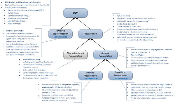
There are different levels of information that can be exchanged in that context, which are listed below:
Figure 1: PMI Definitions
The 3D Mechanical PMI team supports the Industry requirements to have an explicit 3D Geometric Shape Representation with associative 3D Product & Manufacturing Information presented in an ISO 10303 AP203, AP214, or AP242 file formats in a timely manner. Options were to use current enabling technology to support this requirement and to develop the geometric based parts P100, 110 and 115 and phase in the PMI aspects as technology matured as described below.
- Phase I: PMI represented graphically with cross-highlighting capability. The PMI were initially presented as non-semantic Polylines and documented in EN/NAS 9300-120 Ed.1, with support from AP203 Ed.2 and AP214 Ed.3. EN/NAS 9300-120 Edition 2 illustrates the tesselated presentation of PMI which was introduced with AP242.
- Phase II: PMI represented as semantic STEP entities that are fully associative to the Geometric Shape Topology. This is documented in EN/NAS 9300-121 and aligned with AP242.
Manufacturing Feature Domain: Parts 130, 131, 132
Goals and Objectives
The objective of the manufacturing feature domain is to define the requirements for the long term digital preservation of the presentation of characteristics used to define manufacturing features. The purpose of manufacturing features is to facilitate the identification of manufacturing shapes that are human and computer interpretable. This includes machining features, the representation and presentation of holes and fasteners, mechanical installation and assembly joint.
The LOTAR Family of Standards for 3D Mechanical
The planned NAS / EN 9300-1xx standards for the Long Term Preservation of 3D CAD Geometry with Product & Manufacturing Information (PMI) include the following:
| Part | Title | Status |
|---|---|---|
| 100 Ed.1 | Common concepts for L-T Archiving and retrieval of CAD 3D mechanical information | Rel 2012 |
| 100 Ed.2 | Common concepts for L-T Archiving and retrieval of CAD 3D mechanical information | Rel 2024 |
| 110 Ed.1 | L-T Archiving and Retrieval of CAD mechanical 3D Explicit geometry information | Rel 2012 |
| 110 Ed.2 | L-T Archiving and Retrieval of CAD mechanical 3D Explicit geometry information | Rel 2016 |
| 110 Ed.3 | L-T Archiving and Retrieval of CAD mechanical 3D Explicit geometry information | Rel 2025 |
| 115 Ed.1 | L-T Archiving of Explicit CAD assembly structure | Rel 2012 |
| 115 Ed.2 | L-T Archiving of Explicit CAD assembly structure | Planned |
| 120 Ed.1 | L-T Archiving & Retrieval of CAD 3D Explicit Geometry with Graphic PMI Presentation | Rel 2012 |
| 120 Ed.2 | LT Archiving & Retrieval of CAD 3D Explicit Geometry with Tessellated PMI Presentation | Rel 2019 |
| 121 Ed.1 | LT Archiving & Retrieval of CAD 3D Explicit Geometry with Semantic PMI Representation | Rel 2019 |
| 125 Ed.1 | Explicit CAD assembly structure with Graphic Product and Manufacturing Information (PMI) | Rel 2019 |
| 126 Ed.1 | Explicit CAD assembly structure with Semantic Product and Manufacturing Information (PMI) | Planned |
| 132 Ed.1 | Structural joins for assemblies & installation | In draft |
Associated ISO 10303 Information Models
The LOTAR standards do not define specific information models for Long Term preservation of CAD and PDM information models. They rely closely on the ISO 10303 STEP Application Protocols. The STEP modular architecture ensures the consistency of the information models subsets common to several ISO 10303 standards.
The LOTAR P1xx family is based on:
- ISO 10303-242 “Managed Model-Based 3D Engineering”
- ISO 10303-203 “Configuration-Controlled design”
- ISO 10303-214 “Automotive Design”
- ISO 10303-42 “Product data representation and exchange”
- ISO 10303-47 “Shape Variation Tolerances”
- ISO 10303-59 “Quality of Product Shape Data”
Meetings
The Mechanical 3D CAD with Product and Manufacturing Information (PMI) Workgroup holds bi-weekly web meetings / conference Calls.
Contacts
Please use the contact form to get in touch with us if you would like more information about the team, workgroup activities and output, or discuss participating in the topic. The team co-chairs are:
Workgroup Leader Europe
Pierre Duchier
Airbus
Workgroup Leader Americas
Stuart Galt
The Boeing Company


